Mica Dielectric Insulation in Capacitor Energy Storage: What Actually Matters
Energy storage capacitors operate under brutal electrical stress. High ripple currents, rapid charge-discharge cycles, and intense localized heating push insulation materials to their limits faster than almost any other component in a power system. That’s why mica-based dielectrics have dominated capacitor insulation for decades — not because they’re trendy, but because they simply handle energy differently than polymer films or paper.
But applying mica dielectric in energy storage capacitors isn’t just slapping tape between foils. The winding geometry, layer count, thermal management, and voltage distribution all interact in ways that determine whether your capacitor lasts ten years or ten minutes.
Why Mica Outperforms Film and Paper in Pulsed Energy Applications
When a capacitor discharges a massive pulse — think pulsed power systems, defibrillators, or grid-level energy buffering — the dielectric experiences a sudden, enormous electric field spike. Polymer films like polypropylene or polyester respond by stretching at the molecular level. That stretching creates localized thinning. Do it a million times and you’ve got a weak spot waiting to short out.
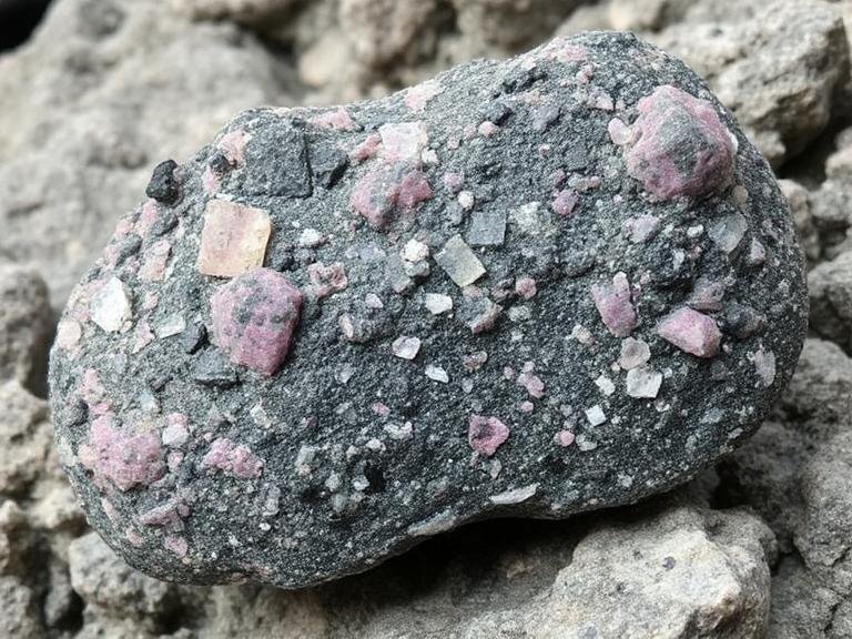
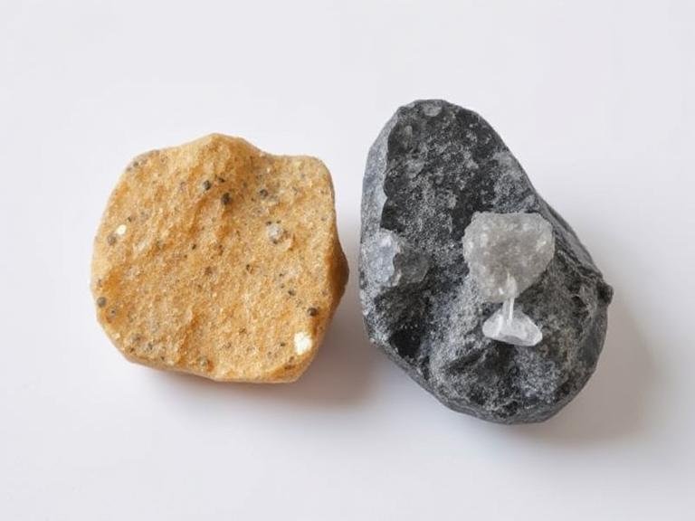
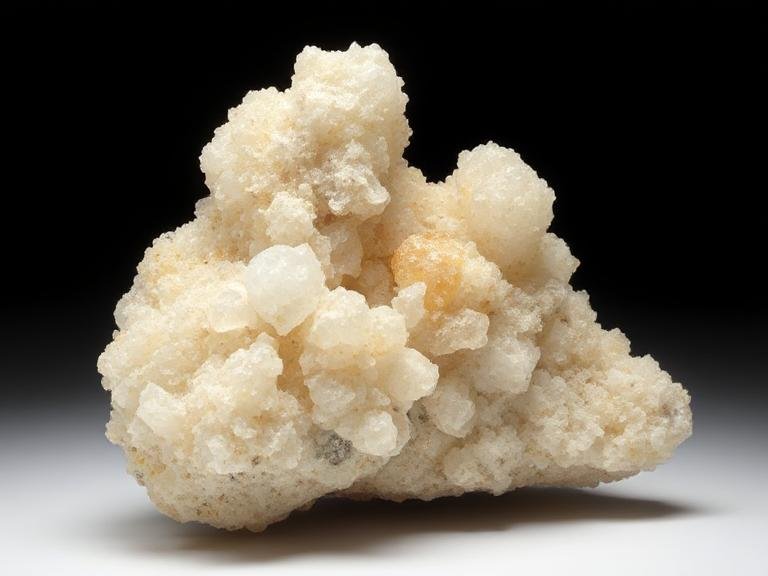
Mica doesn’t stretch. It’s a crystalline mineral with a layered silicate structure that resists deformation under electrical stress. When the field spikes, mica holds its shape. The dielectric constant stays stable, the breakdown voltage doesn’t droop, and there’s no mechanical fatigue from repeated pulsing.
This is why high-energy pulse capacitors almost universally use mica or mica-composite dielectrics. The energy density per unit volume isn’t the highest — film capacitors win on raw capacitance in small packages. But when you need to store and release energy repeatedly under high stress, mica’s dimensional stability and thermal resilience make it irreplaceable.
The tradeoff is thickness. Mica dielectric layers are thicker than polymer films for the same capacitance, which means fewer layers fit in the same volume. That’s why mica capacitors tend to be physically larger than their film equivalents for the same rating. But in energy storage where reliability under stress matters more than size, that tradeoff is worth it.
Layer Stacking and Voltage Distribution in Multi-Mica Capacitors
A single sheet of mica can handle roughly 100 to 150 volts per mil of thickness before breaking down. In a high-voltage energy storage capacitor, you need dozens or even hundreds of volts across the dielectric stack. That means layering many mica sheets with conductive foil electrodes between each one.
The critical part isn’t just stacking — it’s ensuring the voltage divides evenly across every layer. If one layer sees 10% more voltage than its neighbors, it degrades faster, its breakdown voltage drops, it takes even more voltage, and the whole stack cascades toward failure.
This is where the contact area between foil and mica becomes everything. The foil must cover the entire mica sheet with no overhang, no gaps, and no wrinkles. A foil edge that lifts even 0.5mm from the mica surface creates a fringe field concentration at that edge. Under pulsed operation, that concentration ionizes the surrounding medium and starts a partial discharge that eats through the mica from the edge inward.
Use foil that’s slightly smaller than the mica sheet — typically 1 to 2mm undersized on all sides. This prevents edge overlap that could cause inter-layer shorting during winding. The foil should be bonded to the mica with a thin layer of compatible adhesive or vacuum-deposited metal coating. Spray adhesion works well for thin foils because it creates a uniform bond without pooling.
For stacked assemblies, press the layers together under controlled pressure — around 0.5 to 1 MPa depending on the number of layers. Too little pressure and air gaps form between layers, creating voids that partial discharge into. Too much pressure and you crush the mica flakes, reducing dielectric strength and making the stack brittle.
Thermal Behavior of Mica Dielectrics Under Repetitive Charge Cycles
Energy storage capacitors generate heat. Not a lot per cycle, but when you’re cycling thousands of times per hour, that heat accumulates. Mica has excellent thermal conductivity along its crystal planes — roughly 0.5 to 0.8 W/mK for muscovite, much higher for synthetic mica variants. That’s orders of magnitude better than polypropylene film at 0.2 W/mK.
This thermal conductivity matters because it spreads the heat laterally across the dielectric rather than letting it concentrate at the electrode edges where current density is highest. In film capacitors, that edge heating creates thermal runaway zones. In mica capacitors, the heat dissipates sideways into adjacent layers, keeping peak temperatures lower.
But there’s a catch. Mica’s thermal conductivity is anisotropic — it conducts heat well along the planes but poorly perpendicular to them. If you stack mica sheets with their crystal planes aligned randomly, the inter-layer thermal resistance spikes. For best thermal performance in a capacitor stack, orient all mica sheets so their crystal planes run parallel to the foil electrodes. This maximizes lateral heat spreading within each layer and minimizes hot spots at the foil-mica interface.
During high-frequency pulsed operation, the skin effect pushes current toward the foil surfaces. That means the foil heats up faster than the mica. The mica acts as a heat sink pulling energy away from the foil. But if the thermal contact between foil and mica is poor — due to inadequate adhesive coverage or trapped air — that heat sinking fails and the foil overheats locally.
Controlling Partial Discharge in Mica-Dielectric Energy Storage
Partial discharge is the silent killer of mica capacitors. It doesn’t cause immediate failure — it erodes the dielectric one tiny discharge at a time over thousands or millions of cycles. By the time you notice capacitance drop or increased dissipation factor, the damage is done.
The main sources of partial discharge in mica capacitors are voids, delaminations, and foil edge effects. Voids form when air gets trapped between mica and foil during stacking. Delaminations happen when the adhesive bond fails under thermal cycling. Foil edge effects occur when the electrode doesn’t fully cover the mica.
Eliminating voids starts with the stacking environment. Work in a clean room or at least a dust-free space. Handle mica sheets with lint-free gloves — skin oils create hydrophobic spots that repel adhesive and trap air. Apply adhesive in a thin, uniform coat using a doctor blade or spray system. Avoid brush application — it leaves streaks and variable thickness.
After stacking, run the assembly through a vacuum degassing step before final encapsulation or potting. Pull vacuum to below 10 millibar for at least 30 minutes. This removes air from micro-voids that weren’t eliminated during stacking. Then backfill with dry nitrogen or argon if the capacitor will operate in a sealed environment.
For foil edge treatment, round the corners of every foil sheet before stacking. Sharp foil edges create field enhancement factors of 3 to 5 times the nominal field strength. A simple die-cutting process with a rounded punch eliminates this. If you’re using foil with burrs from slitting, deburr every sheet with a fine abrasive pad before assembly.
Encapsulation and Environmental Sealing for Long-Term Storage
Mica itself is inorganic and doesn’t degrade from moisture, UV, or most chemicals. The weak link in a mica capacitor is always the interface — where mica meets foil, where adhesive meets mica, where the stack meets the environment.
Encapsulation protects those interfaces. For high-energy pulse capacitors, epoxy potting is standard. The epoxy fills every gap, bonds to the mica and foil, and creates a rigid, moisture-proof shell. But epoxy has a coefficient of thermal expansion that differs from mica. During temperature cycling, the epoxy pulls on the mica stack. If the bond is too rigid, this stress cracks the mica at the edges.
Use a flexible epoxy formulation or add a silicone-based underfill layer between the stack and the outer potting. This compliant layer absorbs the differential expansion and protects the mica edges from mechanical stress.
For capacitors that need to vent — some pulse applications generate gas from partial discharge breakdown products — don’t fully pot the ends. Leave a small vent path or use a breathable membrane over the end caps. Trapped gas inside a sealed capacitor increases internal pressure, which pushes the foil away from the mica and creates new voids. It’s a feedback loop that accelerates failure.
Store finished capacitors in a dry environment below 40% relative humidity. Mica absorbs almost no moisture, but the adhesive layers and foil oxidation do. A desiccant pack inside the shipping container extends shelf life significantly. Avoid temperature extremes — cycling between -20°C and +80°C stresses the adhesive bonds more than steady high temperature does.
Testing Methods That Catch Problems Before Field Failure
Standard capacitance and dissipation factor tests won’t catch early-stage partial discharge damage. You need specialized tests.
Partial discharge inception voltage (PDIV) testing applies a rising AC voltage to the capacitor and listens for discharge events. A healthy mica stack should show no discharge up to at least 1.5 times the rated voltage. If discharge starts below 1.2 times rated, there’s a void or delamination somewhere in the stack.
Impulse voltage testing simulates the actual pulsed operation the capacitor will see in service. Charge the capacitor to rated voltage, discharge it through a resistor to create a damped oscillatory pulse, and repeat for 10,000 cycles minimum. Monitor capacitance and dissipation factor every 1,000 cycles. A drop of more than 2% in capacitance or a 50% increase in dissipation factor means the dielectric is degrading.
Thermal imaging during pulsed operation reveals hot spots that electrical tests miss. Run the capacitor at its rated pulse repetition rate and scan the surface with an infrared camera. Any spot more than 10°C above the average surface temperature indicates poor thermal contact or a localized high-resistance zone in the foil.
For long-term energy storage applications where the capacitor sits charged for hours or days, monitor leakage current continuously. Mica capacitors have extremely low leakage — typically nanoamps. If leakage creeps up over time, it means moisture ingress or adhesive degradation at the interfaces. Catch it early and you can dry out or re-seal the unit. Let it run and you get a slow, invisible death that ends in sudden short circuit.